Difference between revisions of "Baxter head"
(Created page with "For help with 3d printing check out [http://wiki.lofarolabs.com/index.php/Main_Page 3d printing] on the Lofaro labs wiki.") |
|||
| Line 1: | Line 1: | ||
For help with 3d printing check out [http://wiki.lofarolabs.com/index.php/Main_Page 3d printing] on the Lofaro labs wiki. | For help with 3d printing check out [http://wiki.lofarolabs.com/index.php/Main_Page 3d printing] on the Lofaro labs wiki. | ||
| + | |||
| + | These will all fit very nicely with the screws from [http://www.electronickits.com/robot/Bioloid_Premium.htm this] link it is the boiolid bot kit you will need. | ||
| + | |||
| + | You can down load all of the cad files [http://WDMyCloud.device1083053.wd2go.com/api/1.0/rest/file_contents/Public/Lofaro%20Labs/cad%20with%20baxter%20and%20minibot%20files.zip?device_user_id=9466339&request_auth_code=bf96cdbbdc56841ab88da97c8694982cef6037a6441766fa62a1422d3d68292c here.] | ||
| + | |||
| + | [[File:Halo.png]] | ||
| + | |||
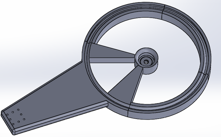
| + | The picture above shows 3 ring1 and 1 ring2 prints they are not connected they are just sitting there they don't need to be connected because the ring1s are just holding the space there. I will explain more later on. | ||
| + | |||
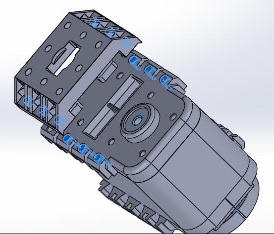
| + | The first thing the you need to do is put N1 nuts in the bracket shown below | ||
| + | * 8 N1 nuts | ||
| + | |||
| + | [[File:Halo.png]] | ||
| + | |||
| + | The next thing to do is to connect the bracket shown above to a servo. this is shown below make sure not to knock out any of the nuts. | ||
| + | * 6 S1 screws | ||
| + | * 6 N1 nuts | ||
| + | |||
| + | [[File:Servo connect.png]] | ||
| + | |||
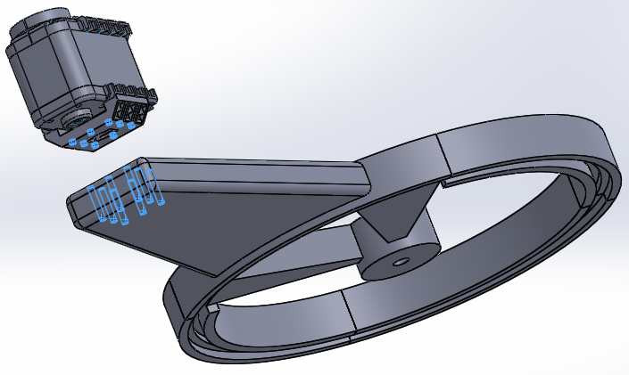
| + | The next part of this is to connect the servo to the halo part. | ||
| + | * 8 S6 screw are required | ||
| + | |||
| + | [[File:Servoandhalo.png]] | ||
| + | |||
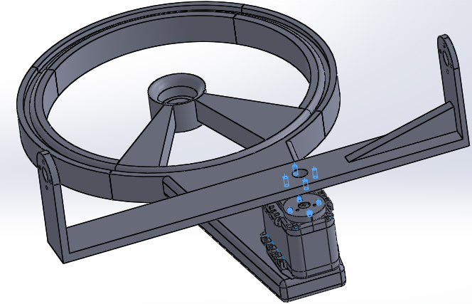
| + | Then 4 S3 screws will be needed to connect the bracket to the servo face as shown below | ||
| + | * 4 S3 screws | ||
| + | |||
| + | [[File:Bracket2.png]] | ||
Revision as of 15:27, 3 December 2014
For help with 3d printing check out 3d printing on the Lofaro labs wiki.
These will all fit very nicely with the screws from this link it is the boiolid bot kit you will need.
You can down load all of the cad files here.
The picture above shows 3 ring1 and 1 ring2 prints they are not connected they are just sitting there they don't need to be connected because the ring1s are just holding the space there. I will explain more later on.
The first thing the you need to do is put N1 nuts in the bracket shown below
- 8 N1 nuts
The next thing to do is to connect the bracket shown above to a servo. this is shown below make sure not to knock out any of the nuts.
- 6 S1 screws
- 6 N1 nuts
The next part of this is to connect the servo to the halo part.
- 8 S6 screw are required
Then 4 S3 screws will be needed to connect the bracket to the servo face as shown below
- 4 S3 screws


