Difference between revisions of "File:Final scheme pcb2.png"
From Lofaro Lab Wiki
(Echung8 uploaded a new version of "File:Final scheme pcb2.png") |
(Echung8 uploaded a new version of "File:Final scheme pcb2.png") |
(No difference)
| |
Revision as of 21:59, 7 December 2015
PCB for our first generation of CRITR. We created this design, with the idea that it would work, but due to limitations by components, mainly the regulators, we weren't able to implement our project without minor amendments. Our 5 volt regulator wasn't able to supply ample amount of current to the h-bridges and to the Raspberry Pi, so we made another pin input to take power directly from the battery supply to the h-bridges.
File history
Click on a date/time to view the file as it appeared at that time.
| Date/Time | Thumbnail | Dimensions | User | Comment | |
|---|---|---|---|---|---|
| current | 21:59, 7 December 2015 | 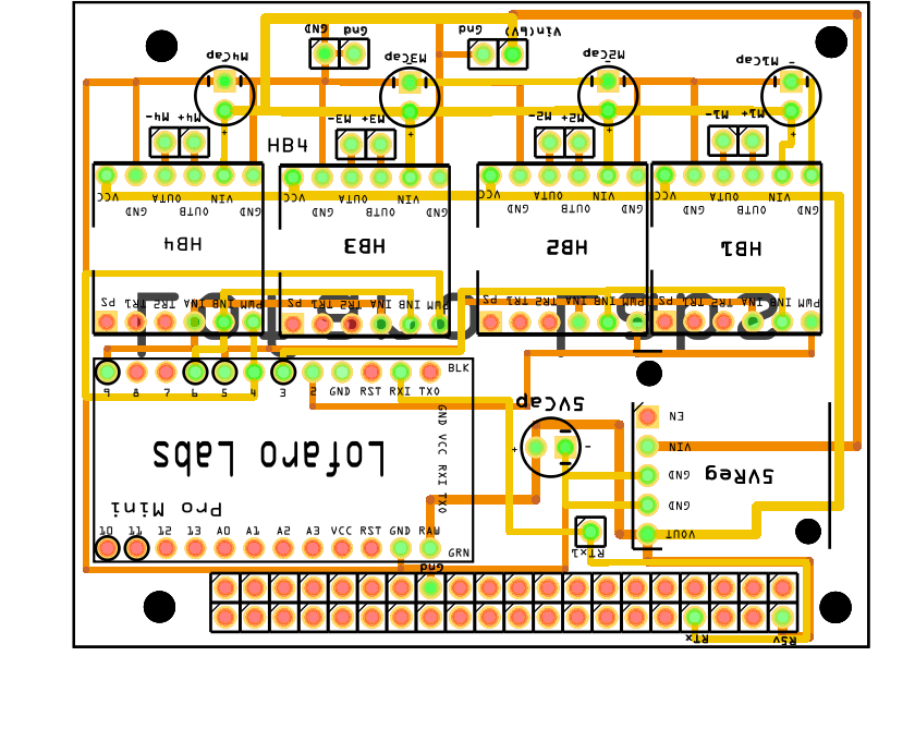 | 840 × 669 (164 KB) | Echung8 (Talk | contribs) | |
| 21:58, 7 December 2015 |  | 840 × 669 (164 KB) | Echung8 (Talk | contribs) | ||
| 20:27, 9 November 2015 | 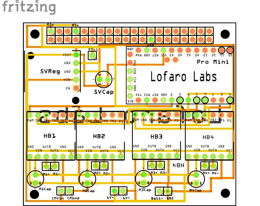 | 840 × 666 (174 KB) | Echung8 (Talk | contribs) | ||
| 20:25, 9 November 2015 | 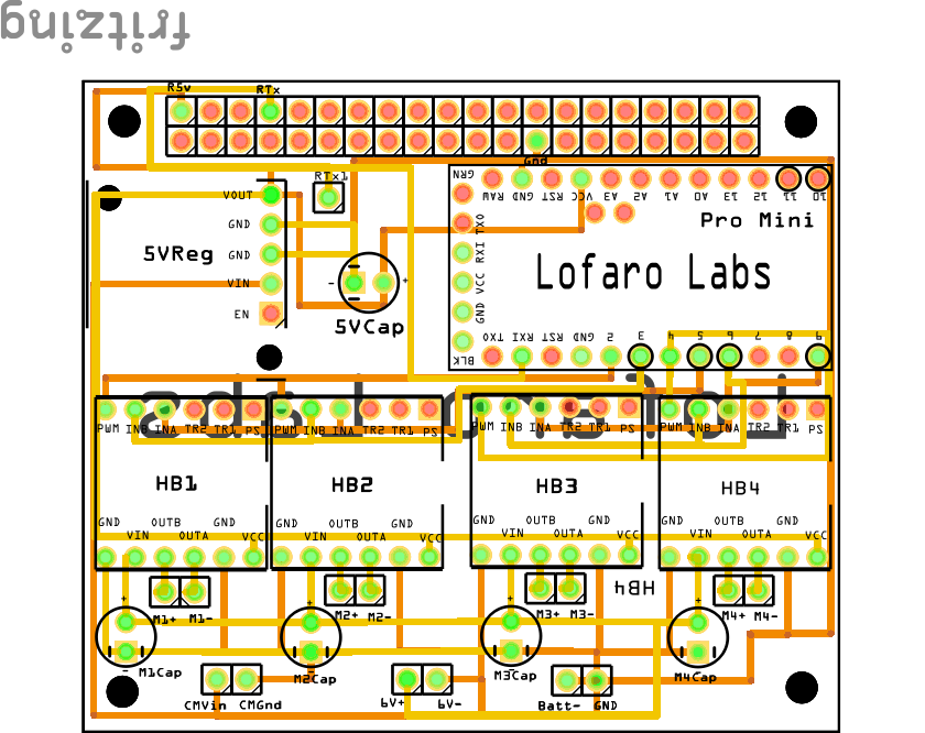 | 840 × 666 (174 KB) | Echung8 (Talk | contribs) | ||
| 20:23, 9 November 2015 |  | 840 × 666 (174 KB) | Echung8 (Talk | contribs) |
- You cannot overwrite this file.
File usage
The following page links to this file: