CRITR/pcb gen1
From Lofaro Lab Wiki
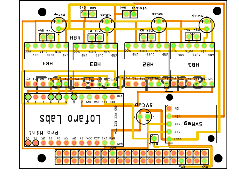
Below is our PCB for our first generation of CRITR. We created this design, with the hopes that it would work, but due to limitations by components, mainly the regulators, we weren't able to implement our project without minor amendments. Our 5 volt regulator wasn't able to supply ample amount of current to the h-bridges and to the Raspberry Pi, so we made another pin input to take power directly from the battery supply to the h-bridges. These changes were made and implemented directly in the CAD design for the second generation, instead of manually amending the PCB board.
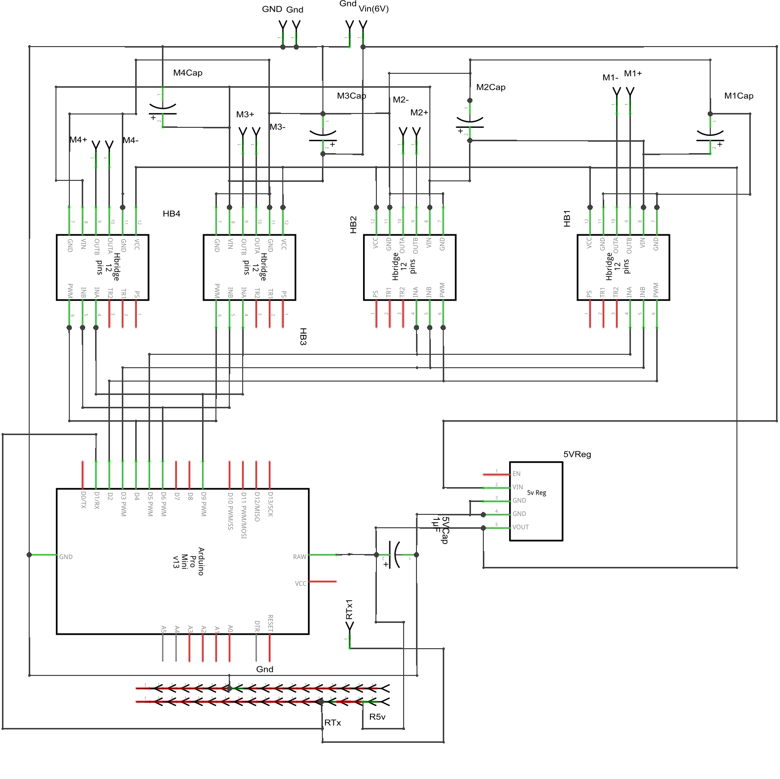
Below is the wiring schematic, showing a different view of how the components connect.

