Minibot Controller/XL-320
From Lofaro Lab Wiki
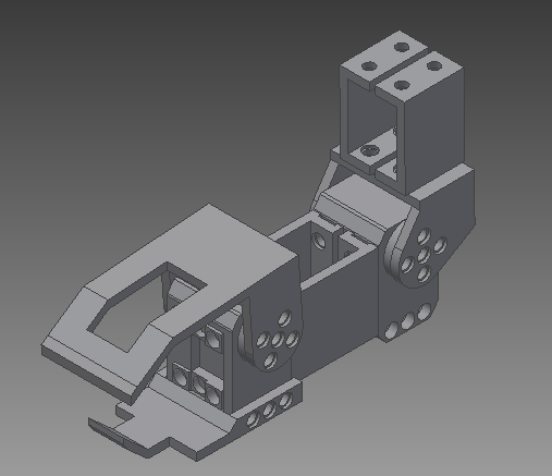
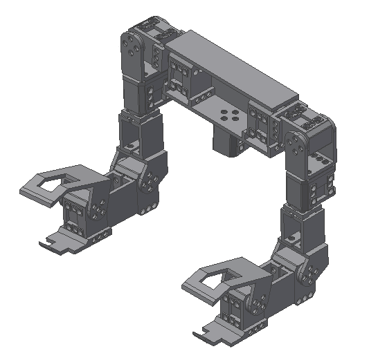
This is the instruction of building the controller for Minibot.
Notes :
- The zero positions will be placed as same as how Minibot is assembled
- - Instruction of Minibot indicates to place zero positions to be at top.
- There are only one arm in the instruction.
- Face the servo as shown in image for one arm.
- Another arm will be mirrored to the instruction.
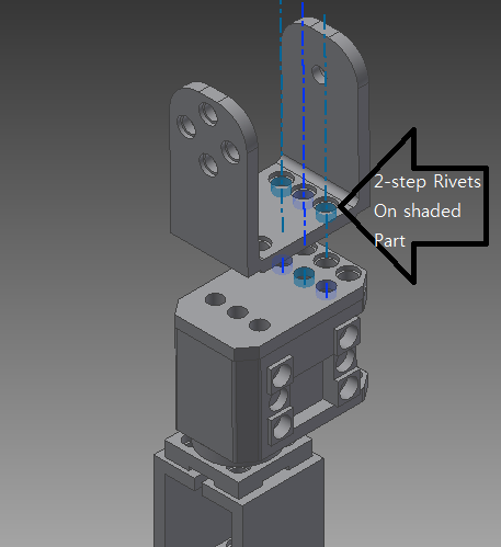
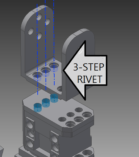
- 2-step rivets are used for all instruction except indicated section.
3D printing :
- STL files are uploaded here.
- You might need to convert STL files to 3D printable file.
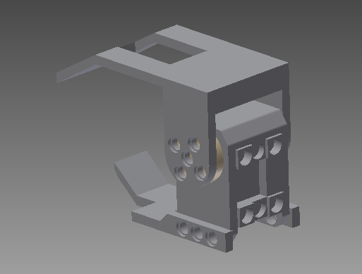
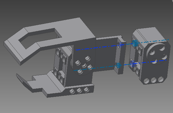
The claw
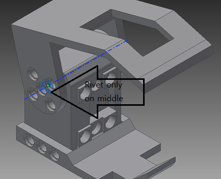
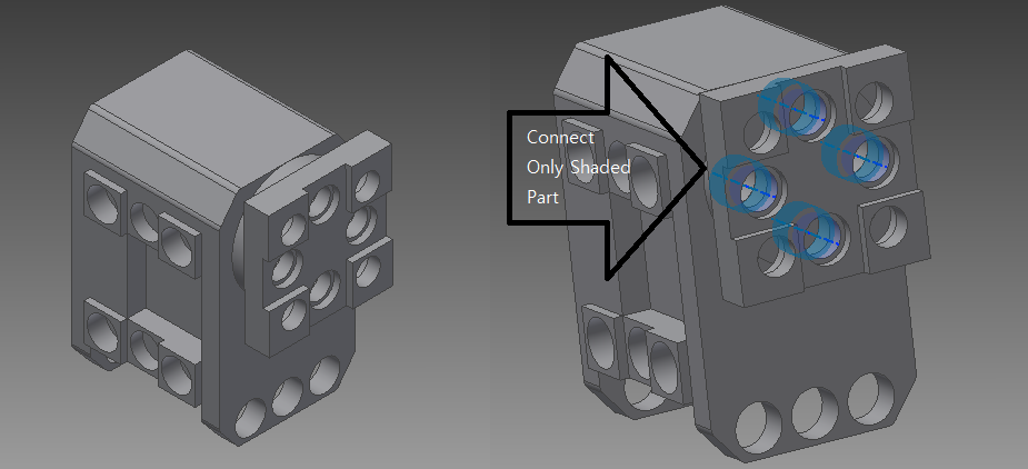
- For movable part of the hand, one of the side of servo will not have wheel; Connect Servo with the hand by putting rivet in the middle hole only.
- On the other side of the servo, For upper hand, put rivets on outer holes.
Forearm
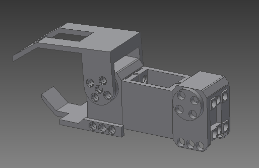
- Before connecting next part, Connect wire to the servo. Then connect Forearm (Part1).
- As Previous part, connect wire before putting forearm.
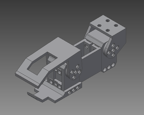
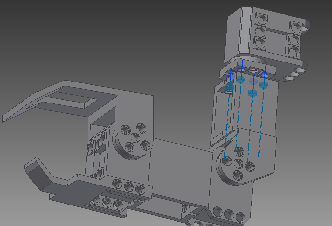
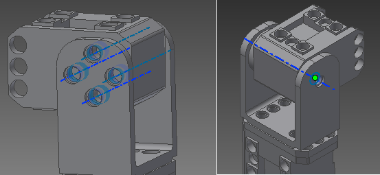
- Connect Elbow part (Part2), similar as you put the upper hand, put 4 rivets on side with wheel, and 1 on the other side.
- Connect Elbow (Part2) with Upper arm (Part3).
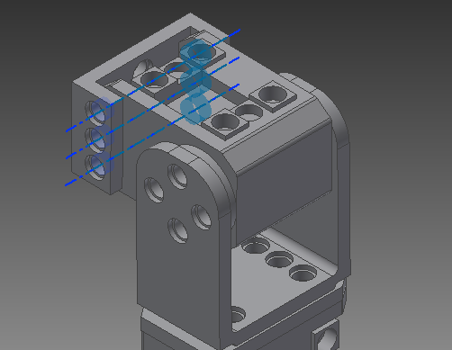
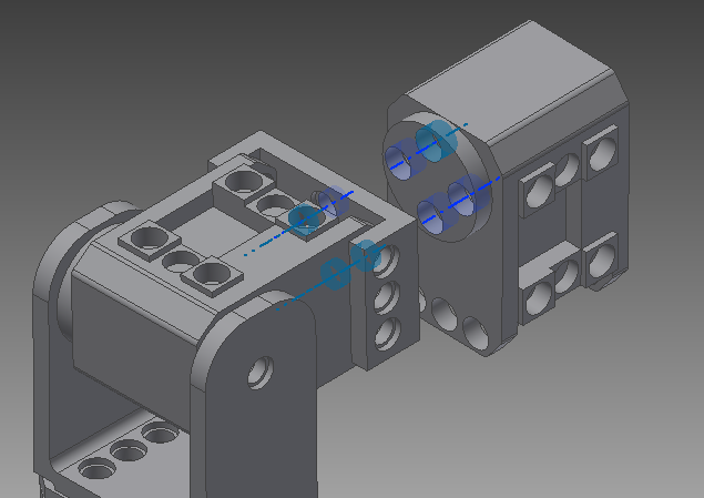
- Connect (Part4) to the servo using indicated holes and rivets.
- Connect (Part4) to Upper arm (Part3).
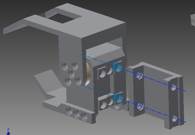
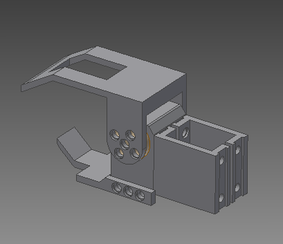
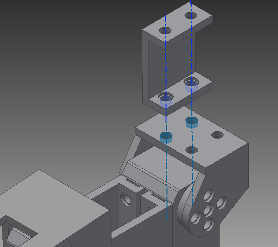
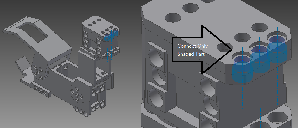
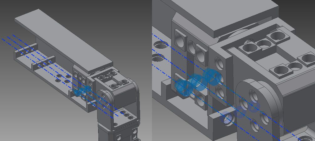
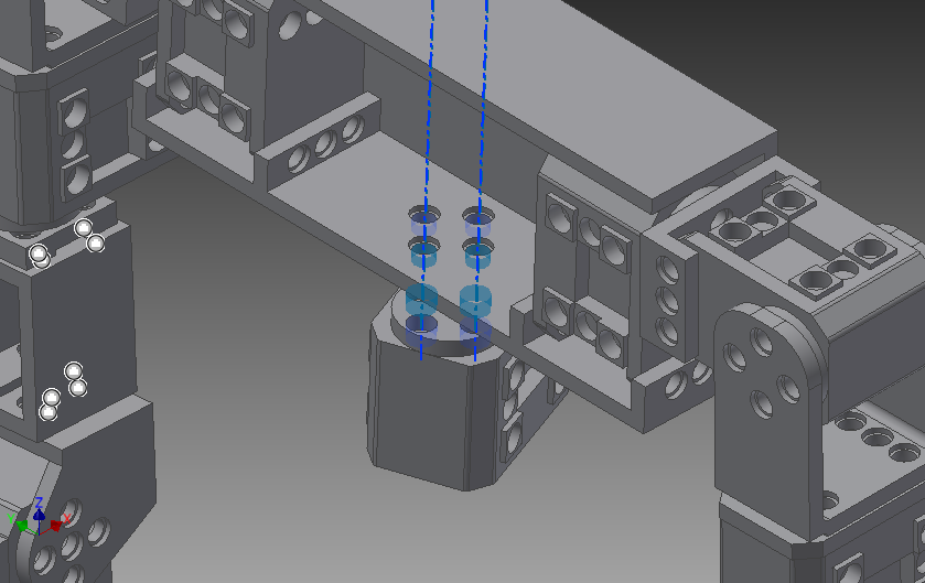
- To connect arm to shoulder, Put (Part5) to arm.
