Difference between revisions of "Robotis Dynamixel XM-430 Based Torque Reactive Joint"
From Lofaro Lab Wiki
(Created page with "=Overview= The robotic joint was design with a gear ratio of 2 to 1. The mount holes on the back of the base match with the mount holes on the limb attachment piece allowing f...") |
(→Resources) |
||
| (6 intermediate revisions by the same user not shown) | |||
| Line 1: | Line 1: | ||
=Overview= | =Overview= | ||
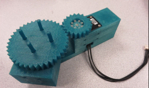
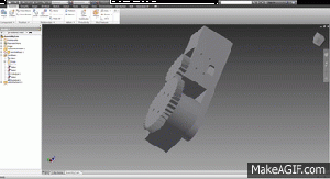
The robotic joint was design with a gear ratio of 2 to 1. The mount holes on the back of the base match with the mount holes on the limb attachment piece allowing for easily connecting multiple joints in series. The parts where design in Autodesk Inventor, dimensions chosen to fit precisely with the model servo, modifications where made to the 3D printed models to allow for the lack of precision in 3D printing. | The robotic joint was design with a gear ratio of 2 to 1. The mount holes on the back of the base match with the mount holes on the limb attachment piece allowing for easily connecting multiple joints in series. The parts where design in Autodesk Inventor, dimensions chosen to fit precisely with the model servo, modifications where made to the 3D printed models to allow for the lack of precision in 3D printing. | ||
| + | |||
| + | [[image:full-assembly-1.png|300px]] [[image:full-assembly-gif.gif|300px]] | ||
=Parts= | =Parts= | ||
==Joint Base== | ==Joint Base== | ||
| − | [[ | + | [[image:joint-base.png|300px]] |
| − | + | ||
| − | + | ||
| − | + | ||
| − | + | ||
| − | + | ||
| − | ==Joint | + | ==Servo and Joint Gears== |
| − | [[ | + | [[image:servo-gear.png|300px]] [[image:joint-gear.png|300px]] |
==Limb Attachment== | ==Limb Attachment== | ||
| − | [[ | + | [[image:limb-attachment.png|300px]] |
==Full Assembly== | ==Full Assembly== | ||
| − | [[ | + | [[image:full-assembly-1.png|300px]] [[image:full-assembly-2.png|300px]] |
| − | [ | + | =Resources= |
| + | * Repository: [https://github.com/MisterHatch/Robotic-Joint https://github.com/MisterHatch/Robotic-Joint] | ||
| + | * Source: [http://mason.gmu.edu/~dhatch2/RobotJoint.html David Hatch GMU] | ||
Latest revision as of 02:15, 22 April 2016
Contents
Overview
The robotic joint was design with a gear ratio of 2 to 1. The mount holes on the back of the base match with the mount holes on the limb attachment piece allowing for easily connecting multiple joints in series. The parts where design in Autodesk Inventor, dimensions chosen to fit precisely with the model servo, modifications where made to the 3D printed models to allow for the lack of precision in 3D printing.
Parts
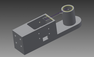
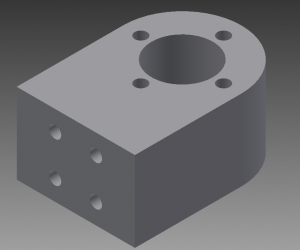
Joint Base
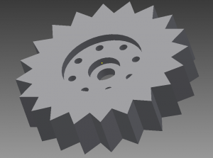
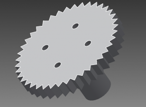
Servo and Joint Gears
Limb Attachment
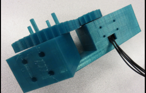
Full Assembly
Resources
- Repository: https://github.com/MisterHatch/Robotic-Joint
- Source: David Hatch GMU
