PCB for IR LED Ring
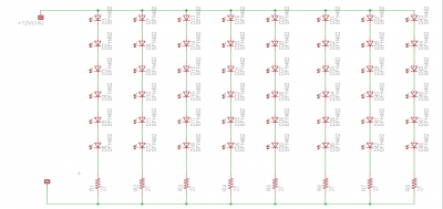
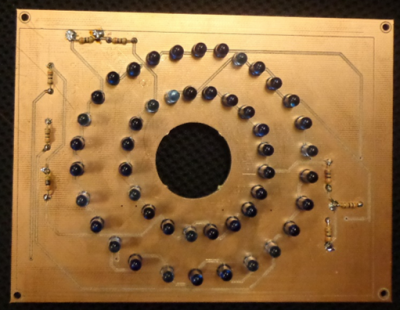
The IR LED ring is a component for this project that is used by the camera attached to POLARIS in order to emit IR light to IR reflective AR tags and localize indoors. The schematic of the IR LED ring is fairly straight forward, which consists of 48 IR LEDs and 8 resistors in order to prevent any issue from occurring.
The number of IR LEDs used to design the IR LED ring was based off the prototype IR LED ring which consisted of approximately 35. The number of IR LEDs was increased for this design in order to increase the radius of the IR light that will emit on the IR reflective AR tags.
This IR LED ring is powered off a 12V, 1A power supply, and each IR LED emits light when the forward current approximately 120 mA. Thus, each branch of the IR LED ring is supplied with approximately 125 mA with a 1A power supply (1000mA/8 = 125 mA). The amount of current that flows through the IR LEDs also affects the angular displacement, or FOV, which is important for emitting the IR light to IR reflective AR tags. Having too much forward current can cause the angular displacement to narrow down, whereas too less forward current can cause the angular displacement to widen too much.
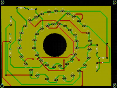
With the aforementioned schematic of the IR LED ring, the next step was to implement it onto a PCB, shown below:
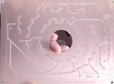
The software used to design the PCB of the IR LED ring was KiCAD. Making sure the connections are correct, the next step was to print the actual PCB and populate it with the actual components.
PCB files used for this project can be found in the following link:
https://github.com/LofaroLabs/POLARIS/tree/master/PCB
For help in designing the PCB for a schematic, the following tutorial is useful:
http://store.curiousinventor.com/guides/kicad/schematic_to_layout/


