Minibot Body
This is part 3 of building Minibot Here we build the chest and waist
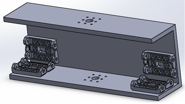
They way I did back was by simply printing it like this so that I didn't need any screws. If you want to add screws you can do it in cad or just drill them out. Another option is gorilla glue it works very well. one problem that I had with printing it as one big part was that I needed to cut out the supports to get the servo to fit just right.
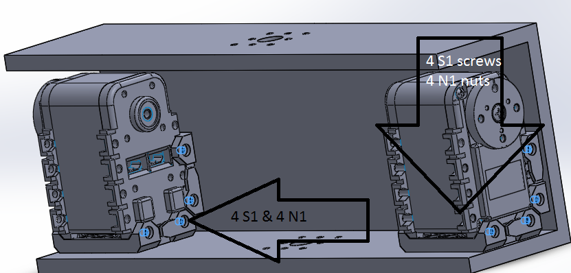
Once you print that back part you need to put in two servos for the arms.
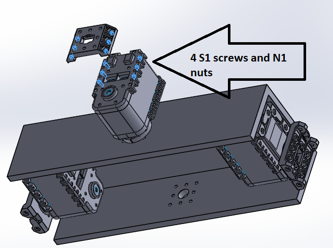
- 8 S1 screws per servo total 16
- 8 N1 nuts per servo total 16
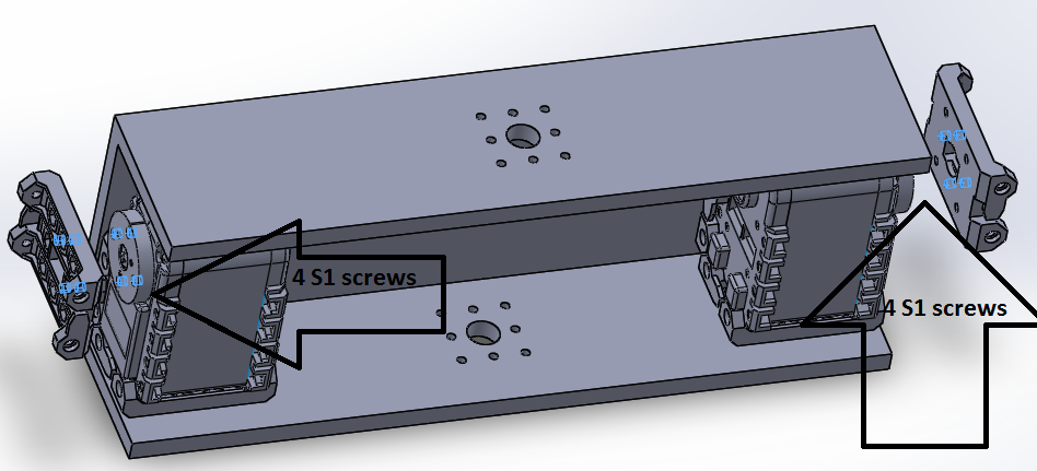
Once the servos are in you need to add the f3 part to the face of the two attached servos as shown below. also remember to make sure that the zero positions are as shown in the figure with respect to the part you are adding
- 8 S1 screws total
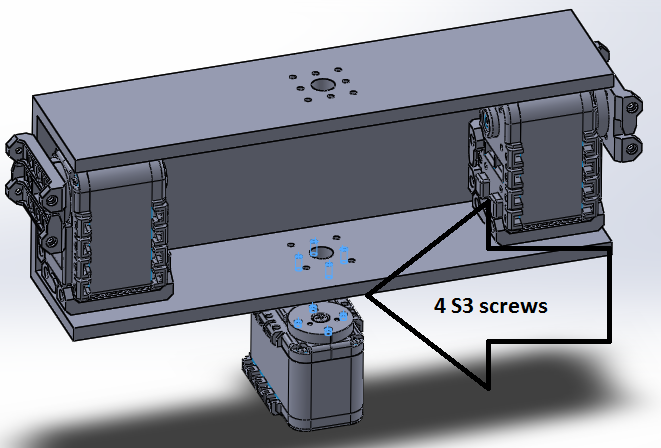
now we connect the waist servo to the back
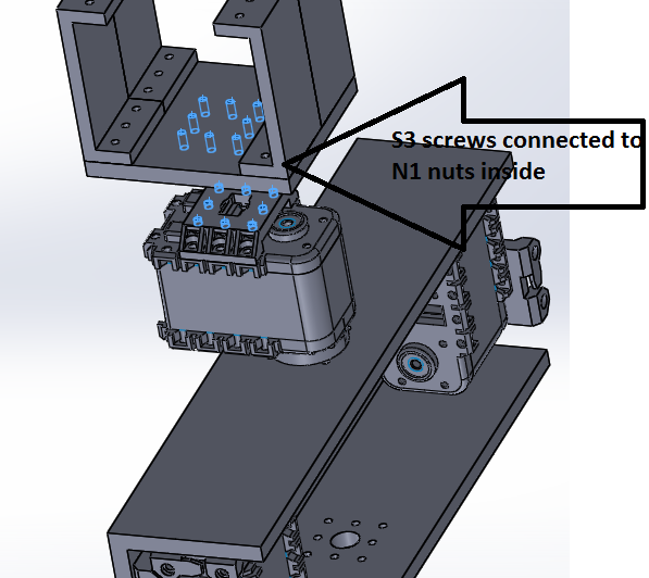
- 4 S3 screws
base
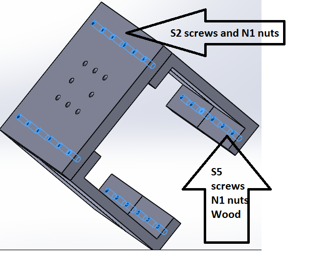
- The base is the part that connects to the wood that sits on the MMP8 moving platform. you will need 12 S5 screws this size will depend on the thickness of the wood that you use. you will also need 12 S2 screws and 24 N1 nuts.
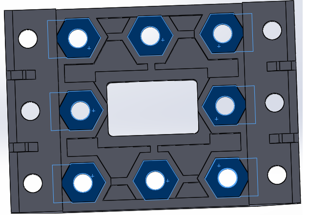
The next part is slightly more confusing you need to put 8 nuts into the part shown below and so that it can be connected to the next part.
After you put in those nuts you need to attach that part to a servo using the other holes because other wise it cannot be connected.
now that you have that attached you need to carefully put in some S3 screws from the base part to the f53 part that should have had the nuts added from above.
- 8 S3 screws
