Final Assembly
Final Arm Construction
To complete the arm we require some new parts, some of which are 3D printed, as well as the other completed components.
Required Components (per arm):
Hand
Wrist
Forearm
Upper Arm
New 3D Printed Components:
Hand Brace
Rotating Hand Brace
Additional Components:
2x grey pegs
1x 4mm x 8mm screw
4x 2mm x 3mm screw
10x 2.5mm x 9mm screw
6x 2.5mm x 12mm screw
7x 2.5mm x 24mm screw
9x nuts
3x 4mm Diameter bearing
Assembly
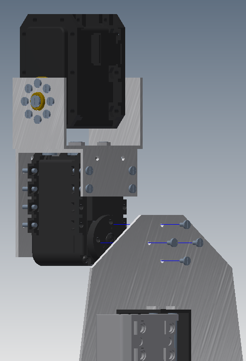
1. First we attach the four holes in the front back of the hand to the AX-12A servo on the wrist as shown in the picture below. This is then secured with 4 2mm x 3mm screws
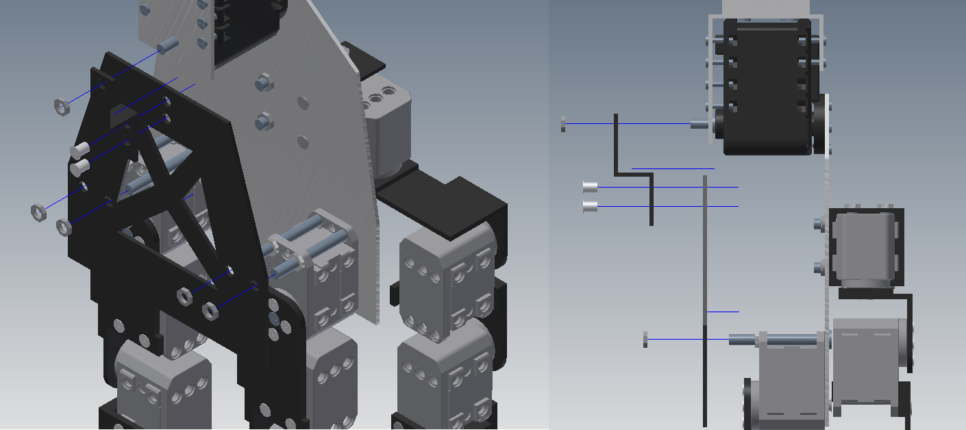
2. Next we attach the Rotating Hand Brace to the Hand Brace in the specified holes using pegs. We then connect the hand brace to the two 4mm x 36mm screws which secure the splay servos on the hand as shown in the figure below. We then secure the the rotating wrist brace to the 4mm x 8mm screw jutting from the back of the wrist with a nut. This provides support for rotation about the wrist yaw.
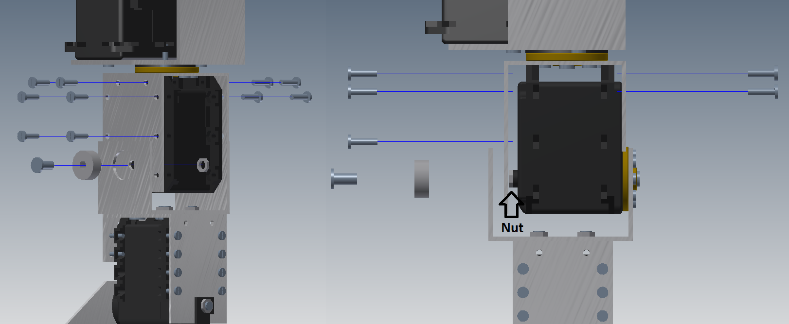
3. In this step we attach the wrist to the forearm by sliding the MX-28T into the wrist rotator and securing it with 6 2.5mm x 9mm screws on the back and 4 2.5mm x 9mm screws on the front. Be sure to keep the FRONT of the servo flush against the rotator. We then carefully slide a nut inbetween the back of the servo and the wrist rotator, which there should be just enough room for if it is completely to the front. We then press the 4mm diameter bearing into the back and use a 4mm x 8mm screw which goes through the bearing and attaches to the nut on the other side of the rotator, thus securing the axis of rotation. Follow the pictures below carefully, notice the nuts position.
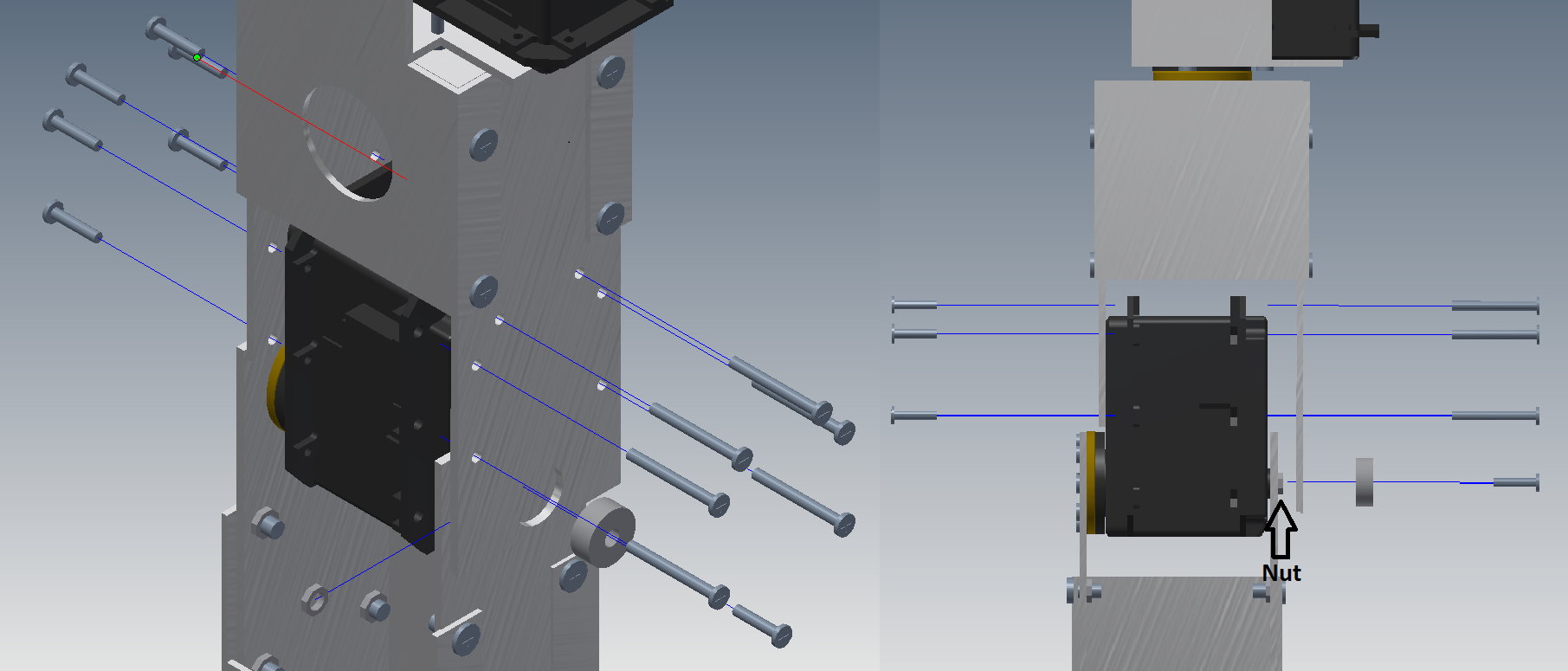
4. In our final step we secure the servo at the top of the lower arm to the upper arm rotator. We attach it using 6 2.5mm x 12mm screws on its front and 6 2.5mm x 24mm screws on its back. Again we keep the front of the servo flush against the rotator so that we can squeeze a nut between the back of it and the bearing. Watch closely for the nut and follow the configuration below. This bearing is mounted with a 4mm x 12mm screw.
If all steps were followed correctly we should have created two arms, a right and a left, that look identical to the two below:


