Build a Robot
Make a model
This tutorial is based off of the tutorial from this page. SDF models can be something as basic as simple shapes or as complex as intricate robots.
Components of SDF Models --Links, Collision, Visual, Inertial, Sensor, Joints, Plugins
Building a Model
1) Collect your meshes Simple shapes are provided in Gazebo (box, sphere, cylinder). Meshes are most commonly used to make your model look realistic. You can look for meshes in Google's 3D warehouse. Or you can create your own meshes using Blender / Sketchup. STL/Collada format is required for mesh files.
2) Make your model SDF file Start with something simple so that if you need to debug, it will be easier than debugging a model you are not familiar with.
First create the model file
gedit box.sdf
Copy the contents below into box.sdf
<sdf version="1.4">
<model name="my_model">
  <pose>0 0 0.5 0 0 0</pose>
  <static>true</static>
    <link name="link">
      <inertial>
        <mass>1.0</mass>
        <inertia> <!-- interias are tricky to compute -->
          <!-- http://answers.gazebosim.org/question/4372/the-inertia-matrix-explained/ -->
          <ixx>0.083</ixx>       <!-- for a box: ixx = 0.083 * mass * (y*y + z*z) -->
          <ixy>0.0</ixy>         <!-- for a box: ixy = 0 -->
          <ixz>0.0</ixz>         <!-- for a box: ixz = 0 -->
          <iyy>0.083</iyy>       <!-- for a box: iyy = 0.083 * mass * (x*x + z*z) -->
          <iyz>0.0</iyz>         <!-- for a box: iyz = 0 -->
          <izz>0.083</izz>       <!-- for a box: izz = 0.083 * mass * (x*x + y*y) -->
        </inertia>
      </inertial>
      <collision name="collision">
        <geometry>
          <box>
            <size>1 1 1</size>
          </box>
        </geometry>
      </collision>
      <visual name="visual">
        <geometry>
          <box>
            <size>1 1 1</size>
          </box>
        </geometry>
      </visual>
    </link>
  </model>
</sdf>
3) Add to model SDF file After each addition, load the model to make sure it is displayed correctly. In what order to add features (suggested, from gazebosim.org tutorials): 1.Add a link. 2.Set the collision element. 3.Set the visual element. 4.Set the inertial properties. 5.Go to #1 until all links have been added. 6.Add all joints (if any). 7.Add all plugins (if any)
Make a Mobile Robot 1) Create directory for your models
mkdir -p ~/.gazebo/models/my_robot
2) Create model.config file
gedit ~/.gazebo/models/my_robot/model.config
3) Copy the following into the file
<?xml version="1.0"?>
<model>
  <name>My Robot</name>
  <version>1.0</version>
  <sdf version='1.4'>model.sdf</sdf>

  <author>
   <name>My Name</name>
   <email>me@my.email</email>
  </author>

  <description>
    My awesome robot.
  </description>
</model>
4) Create a .sdf file
gedit ~/.gazebo/models/my_robot/model.sdf
5) Copy the following into the file
<?xml version='1.0'?>
<sdf version='1.4'>
  <model name="my_robot">
  </model>
</sdf>
Build the Model's Structure -- make changes to ~/.gazebo/models/my_robot/model.sdf
1) Make model static by adding the following under the line containing model name
<static>true</static>
2) Add base by adding the following right under the <static>true</static>
 <link name='chassis'>
            <pose>0 0 .1 0 0 0</pose>

            <collision name='collision'>
              <geometry>
                <box>
                  <size>.4 .2 .1</size>
                </box>
              </geometry>
            </collision>

            <visual name='visual'>
              <geometry>
                <box>
                  <size>.4 .2 .1</size>
                </box>
              </geometry>
            </visual>
          </link>
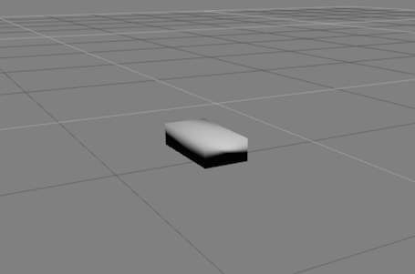
3) Run Gazebo with model to make sure it is displayed correctly. Your model should look like the following
4) Add caster by adding the following under part 2 (caster: sphere with no friction; substitute for wheel which has a joint)
<collision name='caster_collision'>
            <pose>-0.15 0 -0.05 0 0 0</pose>
            <geometry>
                <sphere>
                <radius>.05</radius>
              </sphere>
            </geometry>

            <surface>
              <friction>
                <ode>
                  <mu>0</mu>
                  <mu2>0</mu2>
                  <slip1>1.0</slip1>
                  <slip2>1.0</slip2>
                </ode>
              </friction>
            </surface>
          </collision>

          <visual name='caster_visual'>
            <pose>-0.15 0 -0.05 0 0 0</pose>
            <geometry>
              <sphere>
                <radius>.05</radius>
              </sphere>
            </geometry>
          </visual>
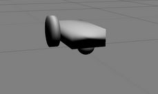
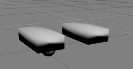
5) Spawn it in Gazebo to make sure it displays correctly. Your model should look like the following:
6) Add left wheel by adding the following under the lines containing geometry, visual, link
<link name="left_wheel">
        <pose>0.1 0.13 0.1 0 1.5707 1.5707</pose>
        <collision name="collision">
          <geometry>
            <cylinder>
              <radius>.1</radius>
              <length>.05</length>
            </cylinder>
          </geometry>
        </collision>
        <visual name="visual">
          <geometry>
            <cylinder>
              <radius>.1</radius>
              <length>.05</length>
            </cylinder>
          </geometry>
        </visual>
      </link>
Your model should look like the following:

7) Add a right wheel by copying the left wheel, by adding the following under the above lines
<link name="right_wheel">
        <pose>0.1 -0.13 0.1 0 1.5707 1.5707</pose>
        <collision name="collision">
          <geometry>
            <cylinder>
              <radius>.1</radius>
              <length>.05</length>
            </cylinder>
          </geometry>
        </collision>
        <visual name="visual">
          <geometry>
            <cylinder>
              <radius>.1</radius>
              <length>.05</length>
            </cylinder>
          </geometry>
        </visual>
      </link>
8) Make the model dynamic by changing the <static> to false and add the following under lines from part 7
  <joint type="revolute" name="left_wheel_hinge">
        <pose>0 0 -0.03 0 0 0</pose>
        <child>left_wheel</child>
        <parent>chassis</parent>
        <axis>
          <xyz>0 1 0</xyz>
        </axis>
      </joint>

      <joint type="revolute" name="right_wheel_hinge">
        <pose>0 0 0.03 0 0 0</pose>
        <child>right_wheel</child>
        <parent>chassis</parent>
        <axis>
          <xyz>0 1 0</xyz>
        </axis>
      </joint>
9) Follow steps 2,3 and 4 towards the bottom of the screen on this link to move the robot around with controllers for each joint
Import Meshes 'Reduce Complexity, Center the mesh, Scale the mesh'
1) Test the Mesh Replace my_mesh.dae with your actual filename of the mesh you wish to test
<?xml version="1.0"?>
<sdf version="1.4">
  <world name="default">
    <include>
      <uri>model://ground_plane</uri>
    </include>
    <include>
      <uri>model://sun</uri>
    </include>
    <model name="my_mesh">
      <pose>0 0 0  0 0 0</pose>
      <static>true</static>
      <link name="body">
        <visual name="visual">
          <geometry>
            <mesh><uri>file://my_mesh.dae</uri></mesh>
          </geometry>
        </visual>
      </link>
    </model>
  </world>
</sdf>
launch Gazebo
gazebo my_mesh.world
Attach Meshes
1) Navigate to directly with model robot
cd ~/.gazebo/models/my_robot
2) Open model.sdf
gedit ~/.gazebo/models/my_robot/model.sdf
3) Add mesh so that the visual with name=visual will now look like
<visual name='visual'>
      <geometry>
        <mesh>
          <uri>model://pioneer2dx/meshes/chassis.dae</uri>
        </mesh>
      </geometry>
    </visual>
4) Drag the My Robot model in the world
5) Scale the visual by adding a scaling factor under the uri
<scale>0.9 0.5 0.5</scale>
6) Raise the visual by adding under visual name = visual
<pose>0 0 0.05 0 0 0</pose>

