Aluminum Machining Tutorial
Using CAM Tools
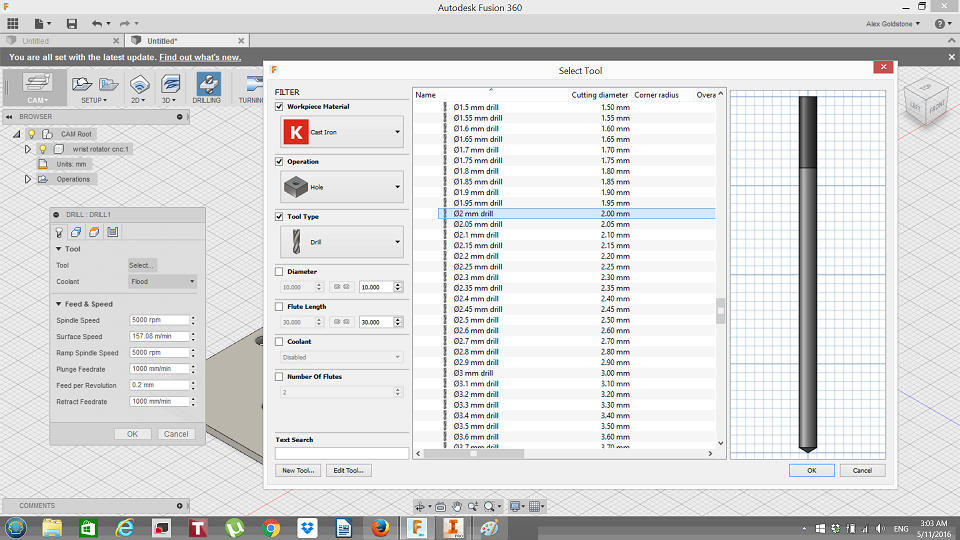
In order to machine parts first you must design your tool path using CAM (Computer Aided Manufacturing) Tools. In this tutorial we will show how to create toolpaths in Autodesk Fusion and export the Gcode for milling.
Setup
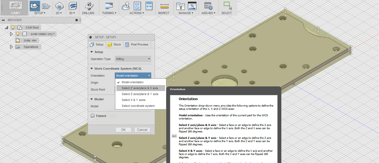
First, go to the file icon at the top menu and select 'New Design from File'. You must select a .stp format file. Once the file is selected on the left of the ribbon a tab should say 'sculpt'. Click the tab and scroll down to select 'CAM'. Just to the right of CAM is the 'setup' option. Click setup and a box should appear that says 'model orientation':
Click model orientation and select the axis you wish to adjust. Set the stock material within the file to match the way if will be placed on your milling machine. Then go to origin and choose selected point. This allows you to select a universal origin for your part. All tools and toolpaths will reference this origin:

