Circuit
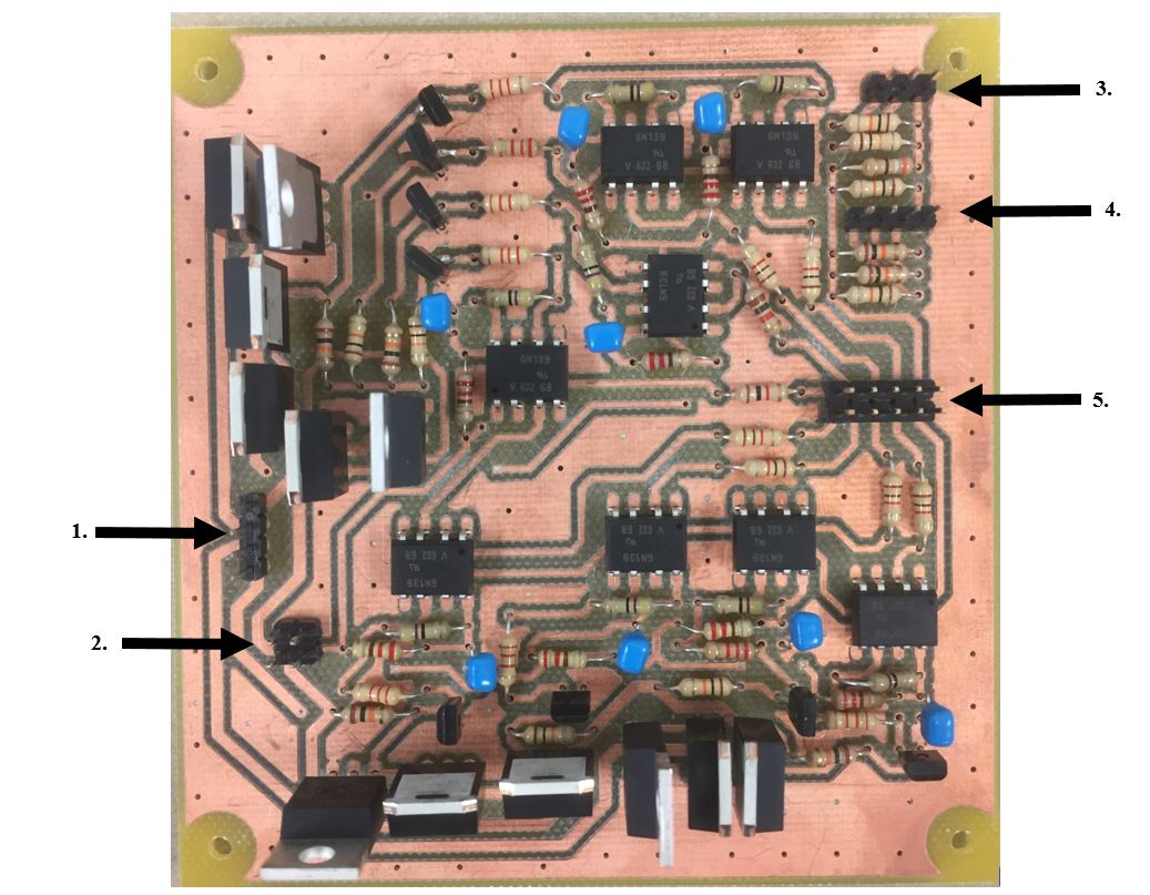
PCB of the H Bridge Circuit with Hall Effect and Encoder Feedback
IO inputs and Outputs
1.
| Motor Output 3 |
| Motor Output 4 |
| Motor Output 1 |
| Motor Output 2 |
2.
| Main Ground | Main Ground |
| Vcc Power | 5V Power |
3.
| Encoder A | Encoder B | Encoder Power |
4.
| Hall Phase A | Hall Phase B | Hall Phase C | MircoSwitch |
5.
| H-Bridge 3 Enable | H-Bridge 3 Direction | H-Bridge 4 Direction | H-Bridge 4 Enable | 5V Encoder |
| H-Bridge 2 Direction | H-Bridge 2 Enable | H-Bridge 1 Direction | H-Bridge 1 Enable | Zynq Ground |
To use the circuit plug the motor into given ports show in arrow 1. For brushed DC motors any two of the half bridges can be used. This means that the circuit can control 2 brushed DC motors. The PWM is sent to the enable FET of the two half bridges used and the direction is sent to the bottom FETS. Since the two bottom FETs are PFET and NFET they will work oppositely thus only 1 will open given a high or low signal. This prevents any shoot through. There is driver circuitry that amplifies the signals up to Vcc to open the FETS. The driver circuitry is a common emitter amplifer. For brushless control plug the three phases into three motor outputs and plug the inputs into three H-Bridge inputs seen in arrow 5.The brushless signals work by sending three different PWM pulses each with a 120 degree phase difference. For the brushless circuit the Hall Effect inputs seen in arrow 4 will be plugged in. For the stepper motor all four motor outputs and H-Bridge inputs needed to be filled. The way the stepper signals work is by creating two Full-Bridges and alternating between the direction on each one. All the code for these signals can be seen in the sources section. When setting up the circuit place the Vcc Power into the Vcc Power pin and give 5V to the optoisolators. The main ground covers the entire circuit and the Zynq chip is plugged into a seperate ground because it is optoisolated. If using Encoders there signals and power can be found in arrow 3. The power for the encoders goes into the 5V encoder pin which then is outputed through the encoder power. This output is what is used to power the encoders on the robot. It is setup like this so the 5V can go through a 39 ohm resistor so the encoders are not burned. Also if the robot has microswitches there is an input for that aswell. Only a firmware update on the FPGA is needed to change the circuit between each motor type. All the code for controlling these motors is on github page located in the sources section.
Parts:
8 10uF Capacitors
8 ZTX692B BJTs
8 6n139 Optoisolators
8 220 Ohm resistors
8 47 Ohm Resistors
8 1k Ohm Resistors
8 10k Ohm Resistors
8 IRF5210SPBF
4 IPP_B80N08S2L_7
Circuit Schematics
The entire circuit showing all part connections.
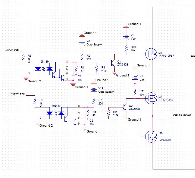
Zoom in on a single half bridge. There are four of these in the circuit.
Datasheets:
http://www.vishay.com/docs/83605/6n138.pdf
http://www.infineon.com/dgdl/irf5210spbf.pdf?fileId=5546d462533600a4015355e35f77198e
http://www.alldatasheet.com/datasheet-pdf/pdf/34608/ZETEX/ZTX692B.html


